This application note describes how to install a third-party joystick knob with a LiNX gaiter protector.
Introduction
The joystick knob on a LiNX remote module can be replaced if it is broken or is not suitable for the user. The replacement knob can be either another Dynamic Controls knob or a third-party knob. However, if replacing with a third-party knob, a LiNX gaiter protector must also be installed. This application note describes how to install a third-party joystick knob with a LiNX gaiter protector.
| NOTE | Dynamic Controls knobs do not require the installation of a gaiter protector since these are built in as standard. |
The LiNX gaiter protector
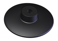
The LiNX gaiter protector (GPL55473), which sits on the joystick shaft above the joystick gaiter and below a third-party knob, is an essential part of the joystick mechanism that:
- protects the gaiter from mechanical damage, and
- protects the controls inside the remote module from foreign matter, especially liquids, that may otherwise run down the joystick shaft.
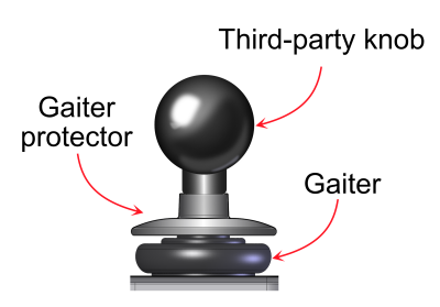
Figure 1: Joystick with example third party knob and gaiter protector installed
Instructions
Step 1 — remove existing joystick knob
Remove the existing knob by pulling it directly away from the main body of the remote module. Some force may be required if the knob is attached tightly to the shaft. DO NOT twist the knob when removing it from the shaft.
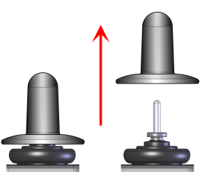 | 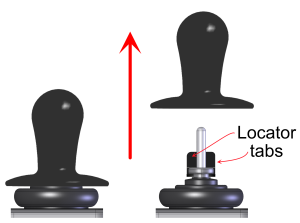 |
Figure 2: Removing the existing knob on the REM400 (left-hand side) and all other remote modules (right-hand side)
| WARNING | Do not use tools or excessive force to remove the knob.Twisting the knob when it is still attached to the shaft may result in damage to the joystick mechanism |
On all remote modules, except REM400, there are two plastic locator tabs (Figure 3 (a)), at the base of the shaft that are used to orientate Dynamic Controls’ knobs. These tabs must be removed before installing a third-party knob and gaiter protector. Note that REM400 remote modules do not have these tabs.
To remove the plastic locator tabs, bend them above the ‘necking’ groove, (Figure 3 (b)), with a pair of pliers. Once removed, only the shoulders of the tabs, that were below the necking groove, will remain, (Figure 3 (c)).
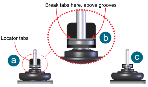
Figure 3: The locator tabs found on all remote modules, except REM400.
Step 2 – place the gaiter protector on the shaft
Place the gaiter protector on the shaft — Figure 4 (a) — and gently rotate it until it locks into place at the bottom of the shaft — Figure 4 (b). Do not move to step 3 if the gaiter protector does not lock into place.
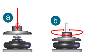
Figure 4: Placing the gaiter protector
Step 3 – place the third-party knob
Place the third-party knob onto the shaft — Figure 5 (a), pressing firmly until it reaches the top of the gaiter protector — Figure 5 (b).
Do not allow any space between the gaiter protector and the knob.
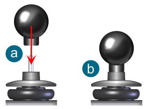
Figure 5: Placing the third-party knob
| WARNING | Do not use tools or excessive force when placing the knob and gaiter protector. |
Testing
Ensure the gaiter protector does not rotate about the shaft — Figure 6 — and ensure there is no gap between the gaiter protector and the third-party knob — Figure 7.
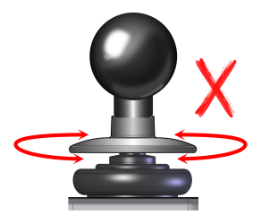
Figure 6: Gaiter protector not locked
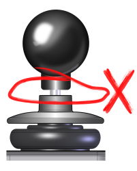
Figure 7: Gap between the gaiter protector and the third-party knob
Test the joystick movement by rotating the joystick in a circular motion about its full extent. It must move freely in all directions and consistently return to the centre, neutral position when released from any position.